Many auto shop owners and operators wonder if the installation of dynamic balancing for wheel balancers on their propellers is a job better left to those who do it often and do it well. We’ve developed a set of basic step-by-step instructions to help you decide whether this is a job you’re willing to tackle.
The basic balancing procedure is as follows:
1. Opening and Checking
Open the package and check whether there are damaged parts. If there are some
problems, please do not use the equipment and contact the supplier. Standard
accessories with equipment are shown as follows:
Screw stud of drive shaft 1
Balancing pliers 1
Allen wrench 1
Measure caliper 1
Locking nut 1
Adapter (cone) 4
Counterweight (100g) 1
Protection hood (optional) 1
2. Installing the machine
2.1 The balancer must be installed on solid cement or similar ground, the unsolidified ground can bring measuring errors.
2.2 There should be 50cm around the balancer in order to operate conveniently.
2.3 Nail anchor bolts on the base’s mounting hole of the balancer to fix the balancer.
3. Installing the hood
Install the frame of the hood on the equipment (optional): plug the pipe of protection
hood into the hood shift (behind the cabinet), then fix with M10×65 screws.
4. Installing screw stud of the drive shaft
Install the screw stud of the drive shaft on the main shaft with an M10 × 150 socket bolt, then screw down the bolt. (Refer to figure 4-1)
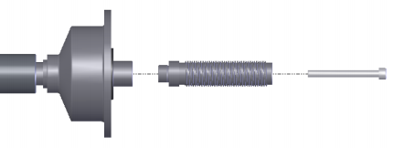
Figure 4-1
(Notice: a wheel can be installed on the main shaft before screwing down, then hold the
wheel by hand in order to prevent the main shaft from revolving together with the bolt.)
5. Installing the LCD screen
Install the LCD on the support with 4 M5 longer screws, and fix the LCD support onto the cover of the cabinet with 2 M5 screws; connect the signal line of the LCD with VGA interface of the cabinet and screw down. Plug the power output port (12V) into the LCD.
6. Installing the wheel
Clean the wheel clear, and no soil left, demount the added Lead weights on the wheel, and then check whether the air pressure in the tire conforms to the stated value, and check whether the locating surface of the rim and the mounting hole are aeroelastic.
 |  |
|---|---|
| Main shaft–wheel (Installing face of rim forward inside) Cone (tip pointing to inside)–fast clamp | Main shaft — spring (it has already been installed when the unit is manufactured) cone (tip point to outside) — wheel Fast clamp |
Tips: do not slip the wheel on the main shaft to prevent the main shaft from scuffing while installing and demounting the wheel.